

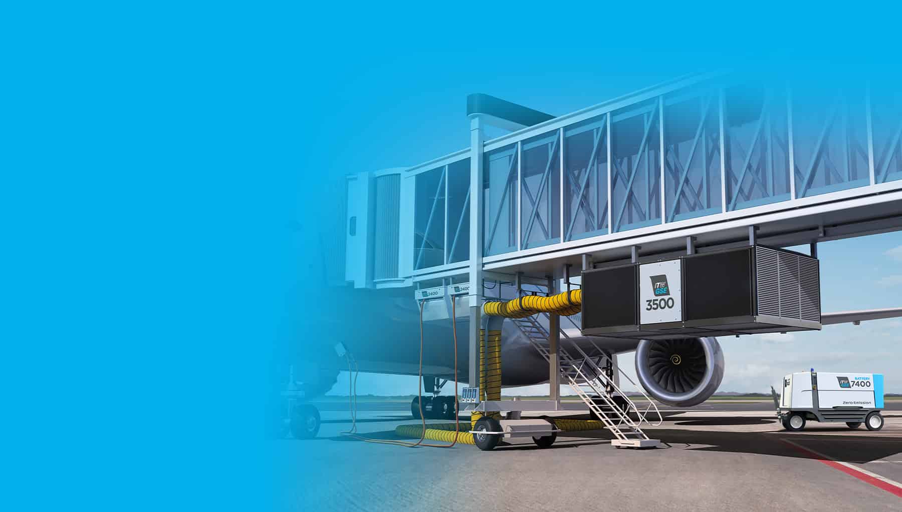


The leading supplier of Ground Power Units, Pre-Conditioned Air Units, Cables and Hoses
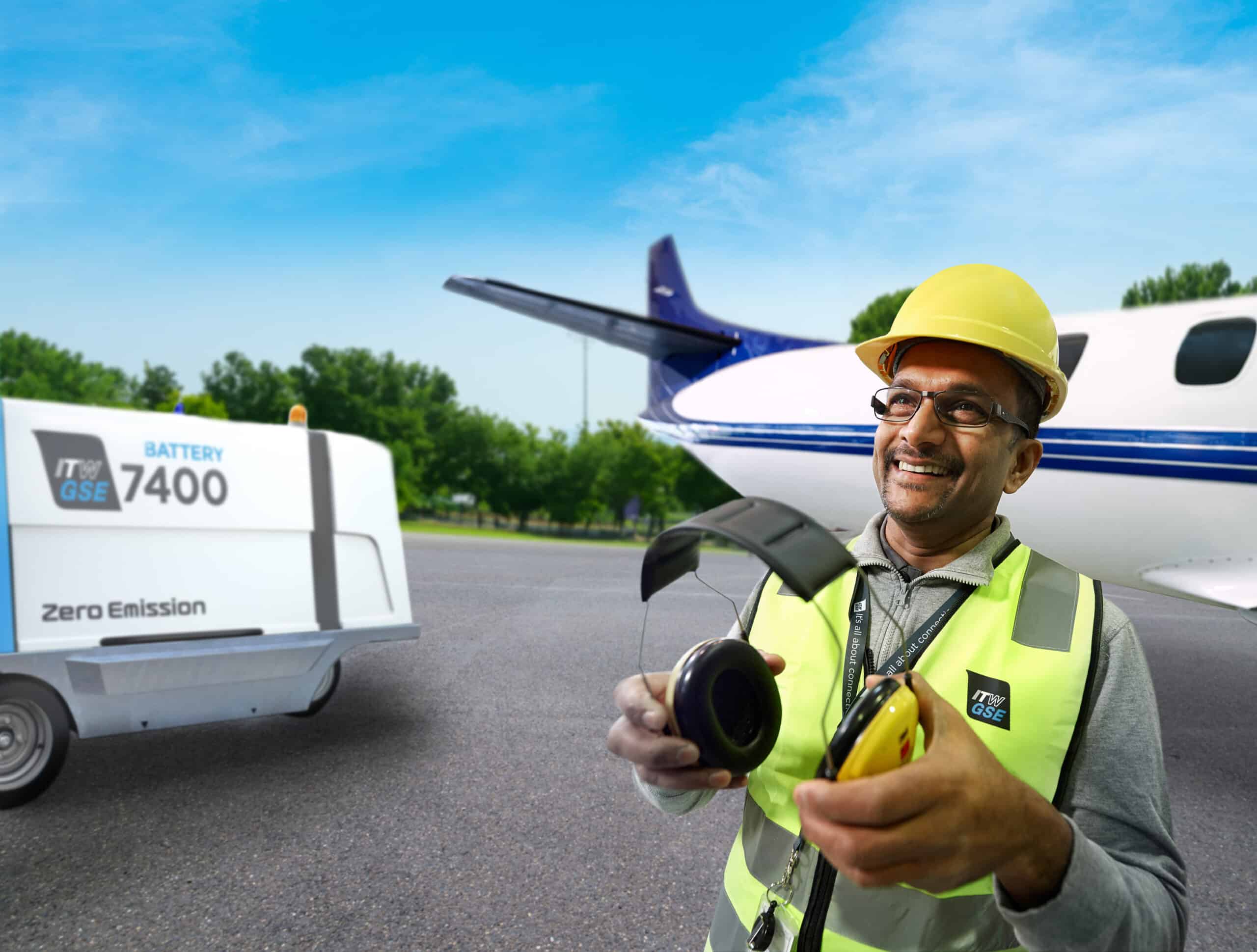
ITW GSE combines customer-back innovation with an in-depth knowledge of the Ground Support Equipment industry to develop and deliver solutions tailored to your needs.
We strive to make best-in-class even better.
We have delivered more than 90,000 units to customers in over 100 countries.
That is experience you can count on.


Customer Support
How can we help you?
Need schematics, spare-part lists or instructional videos? Use the ‘Product Assistance’ button.
Questions for Customer Support? Use the ‘Contact Customer Support’ button.
If your question involves a specific product, please provide the product’s serial number.
News and exhibitions
Feb 22, 2024, posted in News
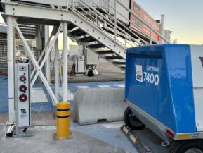
How EcoGate can ease charging challenges
Do you ever wonder how you can scale battery powered ground power units to a larger fleet? One of the questions we often hear...

Feb 06, 2024, posted in News
100 years anniversary celebration for the Danish ITW GSE facility
Hip-hip hooray! Our Danish facility is turning 100 years and we have of course been celebrating! The celebration included a team breakfast in the...
Jan 29, 2024, posted in News
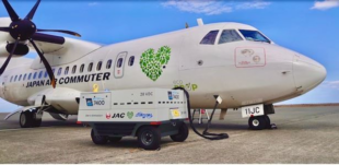
The unique benefits of eGSE
Delve into some of the unique benefits of electrical ground support equipment and discover the challenges associated with adopting eGSE. In a recently published...
EXPO
Apr 28 -
May 01
Apr 28 - May 01, 2024, Exhibition
96th Annual AAAE – Taking Flight Towards a New Horizon
With such a diverse audience of industry leaders how could you miss this event. Industry solutions, continuing education, and certifications. You will definitely find…